 Driving railway vehicles
- Driving rail vehicles biaxial - line 211
- Driving rail vehicles triaxial - A 314
- Driving rail vehicles quadriaxial - A 415
Special driving railway vehicles for light shunting and manipulation with railway wagons designed to ensure technological production operator onsite loading and unloading takes place.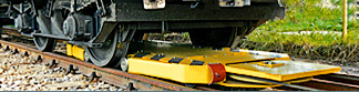 Cable shunting devices
 is designed for the rail cars shunting during their loading and unloading at the sidings, filling stations of liquid products and terminals. The device is able, according to the local conditions, to put in move and to brake the rail cars set with the total weight of up to 2500 t, device PZ 15 of up to 500 tons in both directions.
Cable shunting devices
Cable shunting devices is designed for the rail cars shunting during their loading and unloading at the sidings, filling stations of liquid products and terminals. The device is able, according to the local conditions, to put in move and to brake the rail cars set with the total weight of up to 2500 t, device PZ 15 of up to 500 tons in both directions.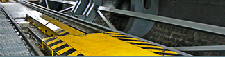 Special equipment
- Dynamic manipulator HW1E
- Electromechanical Train Wheel Stopper EMVZ-02
- Rail locking mechanism KAM-60-8
The dynamic manipulator HW1E has been developed for the wagons rotary tipplers with aim to catch and stop incoming loaded wagons, their appropriate arrangement, and once they are unloaded, their pull out. An important condition is the observance of the velocity of incoming wagons, which can be guaranteed.
Electromechanical Train Wheel Stopper EMVZ-02 has been developed for places on marshalling yards and railway sidings, where the track operator regularly secures the wagons with a wheel stopper.
Rail locking mechanism KAM-60-8 is intended for locking and holding stationary railway wagons on inclined lines during operation with individual wagons.
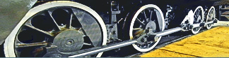
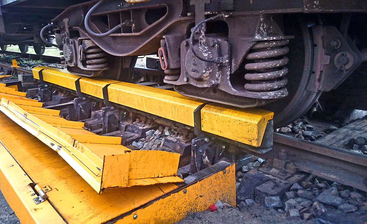
Rail locking mechanism KAM-60-8
This spring-mechanical locking system is intended for locking and holding stationary railway wagons on inclined lines during operation with individual wagons, eg holding them during the replacing of the shunting device when filling or unloading the wagons.
Basic description
The locking system consists of two independent parts – segmental pusching blocks, which are controlled simultaneously from the central switchboard. Each segment pusching block is located separately on one side of the track and attached to the foundation sleepers..
The foundation sleepers are located between the railway sleepers and are attached to the track. Depending on the track gauge 1520 or 1435 mm, two lengths of foundation sleepers are then used.
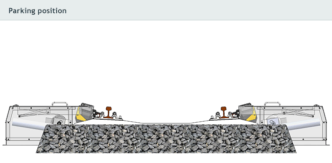
Rail locking mechanism positions
Rail locking mechanism have 3 working positions:
Parking position
It is the position where the segmental pusching blocks of the locking mechanism are opened and inserted in the sheet metal cover, while allowing the free passage of railway wagons and locomotives and thus do not interfere with the passage profile of the track.
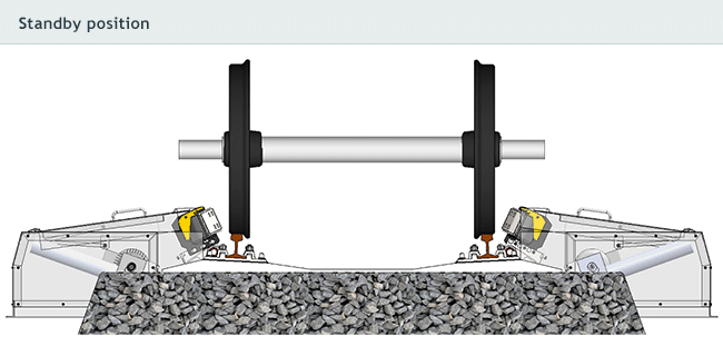
Standby position
There is a position where the locking segments do not come into contact with the wheelset of the wagon, but the segments are located close to the wheelset and the mechanism is ready for the locking command. The standby position serves to react the locking mechanism faster and shorten the time before it moves to the locking position. This position allows the normal passage of railway wagons and the correction of the position of the captured wagon, but does not allow the passage of locomotives.
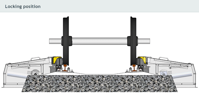
Locking position
The position of the mechanism where the locking segments come into contact with the wheelsets of the caught wagon. The individual locking segments are supported on the wagon wheel, the compressed springs of the segments creating pressure.
Download Type list »
Special equipment
| Type list | Photogallery |
| Basic technical data KAM-60-8 | |
|---|---|
| Manufacturer KAM-60-8 | Kolejové Pohony a.s. |
| Power of electric motors | 2× 4 kW |
| Reaction time | Within 8 seconds from standby to working position |
| Power voltage | 230/400 V, 50 Hz |
| Sensor operating voltage [V] | 10...30 VDC |
| Maximum sustainable traction | 80 kN |
| Optional track gauge | 1435 or 1520 mm |
| Size (l × h × w) | 3930 × 675 × 4275 mm |
| Weight | 3000 kg |

Mostárenská 2917/40
703 00 Ostrava-Vítkovice
Phone: +420 601 302 840
Czech Republic