 Driving railway vehicles
- Driving rail vehicles biaxial - line 211
- Driving rail vehicles triaxial - A 314
- Driving rail vehicles quadriaxial - A 415
Special driving railway vehicles for light shunting and manipulation with railway wagons designed to ensure technological production operator onsite loading and unloading takes place.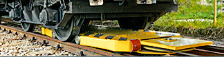 Cable shunting devices
 is designed for the rail cars shunting during their loading and unloading at the sidings, filling stations of liquid products and terminals. The device is able, according to the local conditions, to put in move and to brake the rail cars set with the total weight of up to 2500 t, device PZ 15 of up to 500 tons in both directions.
Cable shunting devices
Cable shunting devices is designed for the rail cars shunting during their loading and unloading at the sidings, filling stations of liquid products and terminals. The device is able, according to the local conditions, to put in move and to brake the rail cars set with the total weight of up to 2500 t, device PZ 15 of up to 500 tons in both directions.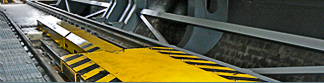 Special equipment
- Dynamic manipulator HW1E
- Electromechanical Train Wheel Stopper EMVZ-02
- Rail locking mechanism KAM-60-8
The dynamic manipulator HW1E has been developed for the wagons rotary tipplers with aim to catch and stop incoming loaded wagons, their appropriate arrangement, and once they are unloaded, their pull out. An important condition is the observance of the velocity of incoming wagons, which can be guaranteed.
Electromechanical Train Wheel Stopper EMVZ-02 has been developed for places on marshalling yards and railway sidings, where the track operator regularly secures the wagons with a wheel stopper.
Rail locking mechanism KAM-60-8 is intended for locking and holding stationary railway wagons on inclined lines during operation with individual wagons.
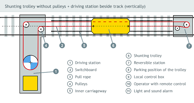
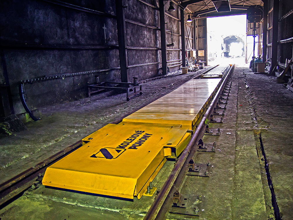
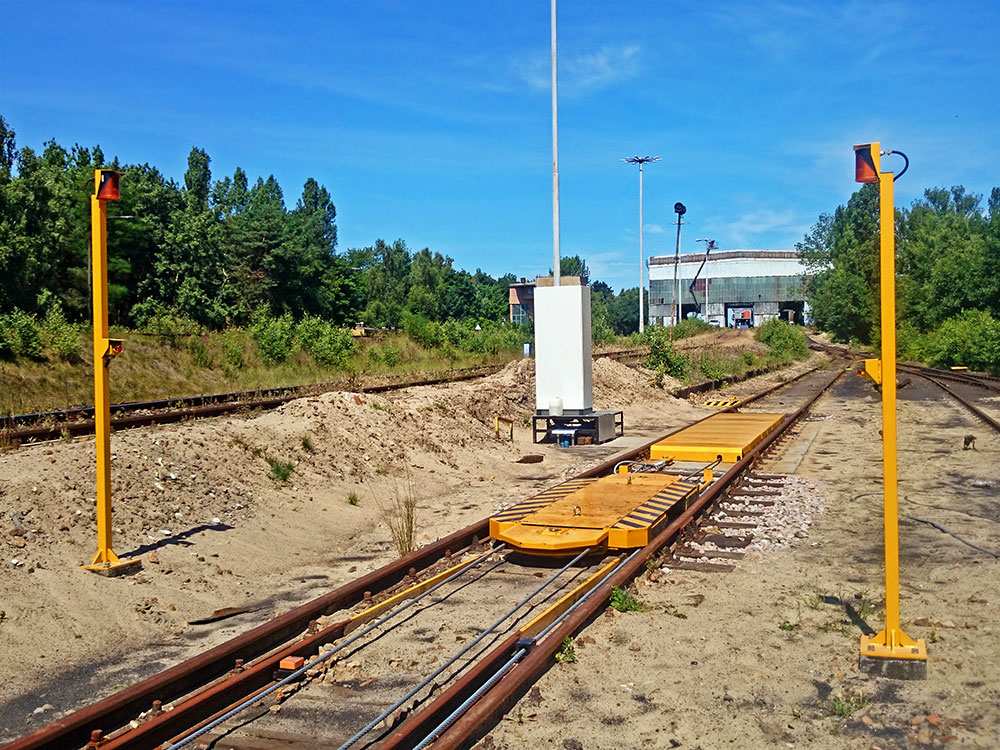
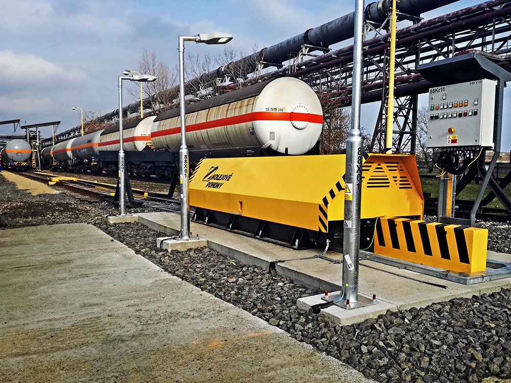
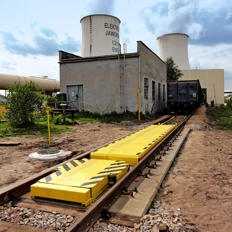
Cable shunting device LTV-PV
The cable shunting device LTV-PV is designed for the rail cars shunting during their loading and unloading at the sidings, filling stations of liquid products and terminals. The device is able, according to the local conditions, to put in move and to brake the rail cars set with the total weight of up to 2000 t.
Basic description
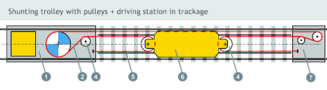
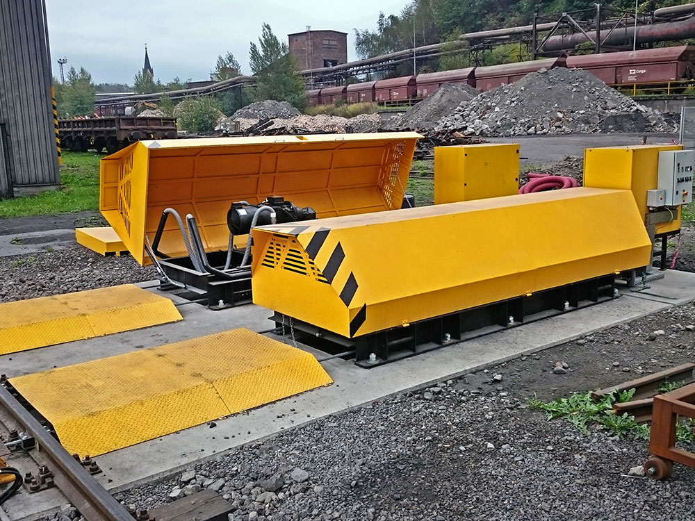
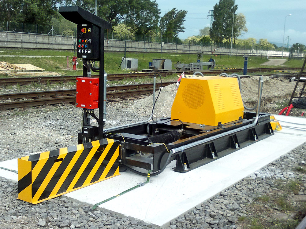
The cable shunting device LTV-PV consists of three basic units - driving station, reversible station and shunting trolley, which is drawn upon its own narrow-gauge track with the help of transport rope.
The pre-stressing in the pull rope is not constant; it varies depending on required function of the shunting trolley. The integral part of supply is switchboard with control system and the rope tightening unit. When out of operation, the trolley travels beneath standing wagons and when switched to operation mode, it extends the arms with pushing rollers in order to pick up the wagon.
Control
The traction and braking of the set of wagons are controlled by frequency converter. The programming automatics in the technology distributor allows for logical links to existing technology equipment such as installed at the siding (filling nozzles and arms, rail scale, etc.).
The whole shunting device technology can be designed for and implemented in the environment marked with the danger of explosion.
Course of shunting LTV-PV
- The shunting locomotive pushes the set of wagons to the shunting device location.
- The operator uncouples the set of wagons from the locomotive, which can travel away in order to perform another tasks.
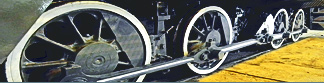
- Operated from a local switch or remote control, the shunting trolley moves underneath the wheelsets and ejects its arms to catch the rail car’s wheelset from both sides.
- It moves a single wagon or more rail cars to a designated place.
- After the wagons are loaded, the operator moves them in the same manner to the place, where they can get coupled with shunting locomotive.
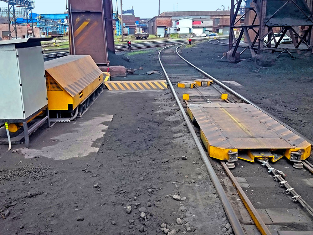
Driving station
Is consists of welded travel frame, which through the use of anchor bolts is anchored to a concrete base where the main drive travels. The drive frame contains driving unit composed of three-phase airt-cooled electric motor and epicyclical gear with driving cable disk attached to the output flange.
Placed on a concrete base of driving station are pulleys, guiding driving rope to the reversible station, shunting trolley and return to the station.
The driving rope’s tightening is effected with help of hydraulic equipment or under assistance of electric actuator.
Reversible station
Consisting of welded frame with attached pulleys and lug - dead eye (in case of “three-rope system” the rope is firmly fixed to the concrete base of the reversible station).
The pulley ensures guidance of the driving rope towards the shunting trolley and back, where it is with the help of harness, dead eye and rope clamps completed. The structure is protected by the steel shield.
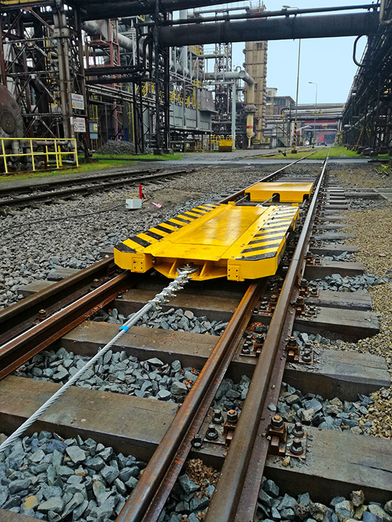
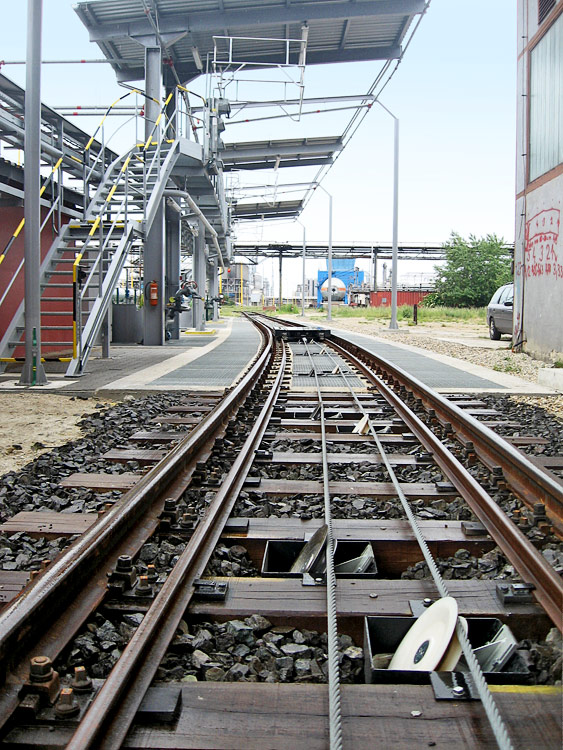
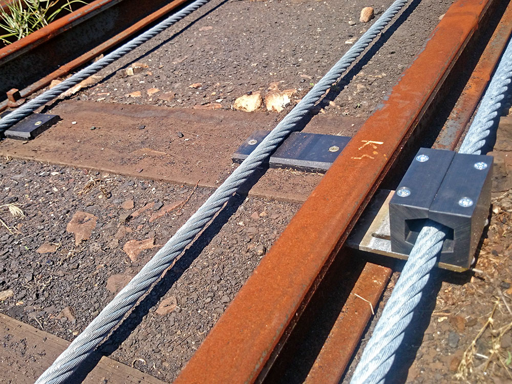
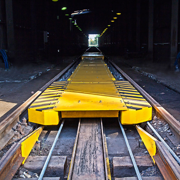
Carriageway and pull rope
The shunting trolley travels underneath railcars upon its own carriageway inside the track age. Its rails are fixed in the work space directly to timber sleepers or to so called fake steel sleepers placed upon the concrete ones. The carriageway has on one side a reduced section and creates so called parking position of the trolley.
When the shunting trolley remains in its parking position, the locomotive can easily travel over it. An unlubricated steel pull rope is designed according to the technical standard STN EN 12385-4 with diameter pursuant to designed load. The movable part of the rope in the trackage is supported by the rollers that reduce the rope’s abrasive wear and keep it clean.
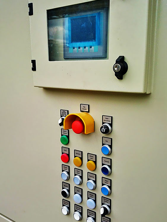
Control
As a standard, the shunting device is controlled with use of local control box that is located on a clear spot beside the track, or from the control panel in the service staff room.
Another possibility is a remote control using radio set. The operator can handle the cars from any place along the track. The service control point is the distribution box itself, which serves only for the needs of maintenance and repairs.
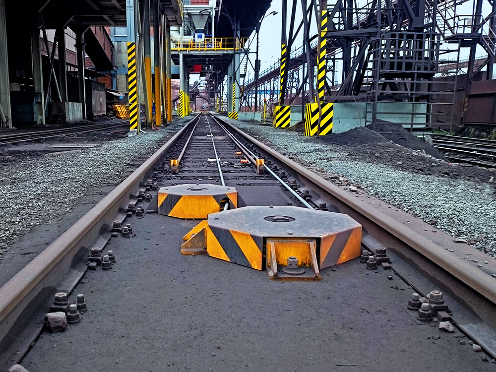
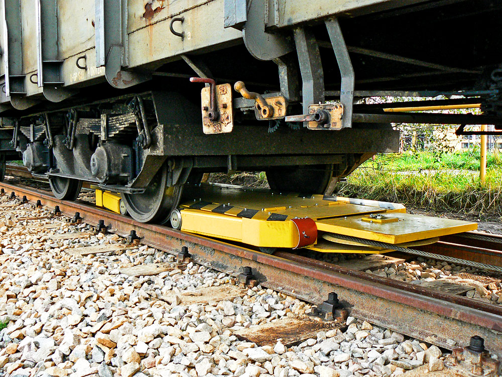
Capture of rail car wheelset
The pre-stressing in the pull rope is not constant; it varies depending on required function of the shunting trolley. In its operation mode, the trolley ejects the pulleys that, once the rail car’s wheelset is captured, roll on the wheelset tyres. After finishing required handling the set of wagons, the operator givers order to reduce pre-stressing and the pulleys are retracting.
Cable device is able to travel underneath the set of wagons.
In order to reduce its abrasive wear, the pull rope’s tow and reversible parts is supported by the assembly of supporting rollers and pulleys placed in the work space of the shunting trolley.

Download Type list »
-->
Fill in the questionnaire for particular specification of the equipment »
Cable devices
| Questionnaire | Type List | Photo Gallery |
| Basic technical data LTV-PV | |
|---|---|
| Tractive power* | 40 - 120 kN |
| Electric motor output | 7.5, 11, 15, 22, 30 kW |
| Max. velocity of trolley* | 0,2 m/s - load less 0,5 m/s - loaded |
| Max. weight of shunted set* | Up to 2 000 t |
| Permissible slope of trackage | max. 3 ‰ |
| Trackage | Shunting possible in arc and at adjusted crossing |
| Control |
|
| *According to local conditions and user’s requirements | |


Mostárenská 2917/40
703 00 Ostrava-Vítkovice
Phone: +420 601 302 840
Czech Republic