 Driving railway vehicles
- Driving rail vehicles biaxial - line 211
- Driving rail vehicles triaxial - A 314
- Driving rail vehicles quadriaxial - A 415
Special driving railway vehicles for light shunting and manipulation with railway wagons designed to ensure technological production operator onsite loading and unloading takes place.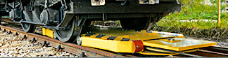 Cable shunting devices
 is designed for the rail cars shunting during their loading and unloading at the sidings, filling stations of liquid products and terminals. The device is able, according to the local conditions, to put in move and to brake the rail cars set with the total weight of up to 2500 t, device PZ 15 of up to 500 tons in both directions.
Cable shunting devices
Cable shunting devices is designed for the rail cars shunting during their loading and unloading at the sidings, filling stations of liquid products and terminals. The device is able, according to the local conditions, to put in move and to brake the rail cars set with the total weight of up to 2500 t, device PZ 15 of up to 500 tons in both directions.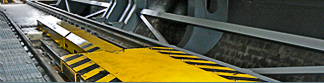 Special equipment
- Dynamic manipulator HW1E
- Electromechanical Train Wheel Stopper EMVZ-02
- Rail locking mechanism KAM-60-8
The dynamic manipulator HW1E has been developed for the wagons rotary tipplers with aim to catch and stop incoming loaded wagons, their appropriate arrangement, and once they are unloaded, their pull out. An important condition is the observance of the velocity of incoming wagons, which can be guaranteed.
Electromechanical Train Wheel Stopper EMVZ-02 has been developed for places on marshalling yards and railway sidings, where the track operator regularly secures the wagons with a wheel stopper.
Rail locking mechanism KAM-60-8 is intended for locking and holding stationary railway wagons on inclined lines during operation with individual wagons.
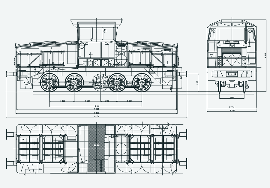
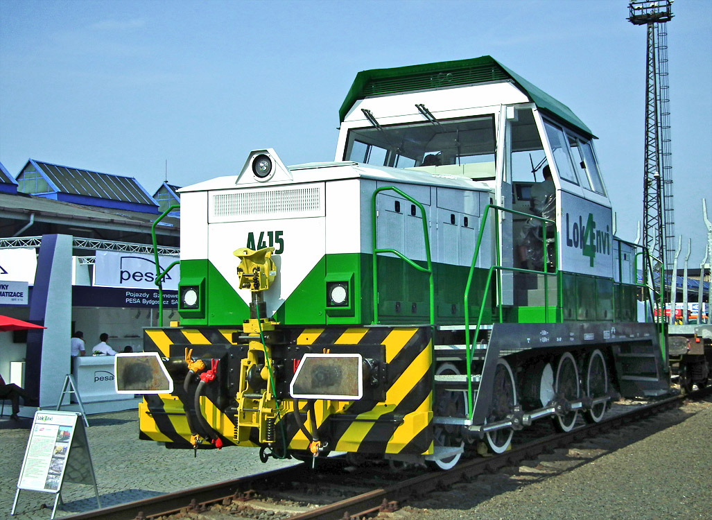
Driving rail vehicles quadriaxial - A 415
The concept of new quadriaxial electric shunting locomotive A 415 fed from traction accumulators originates from already tested threeaxial locomotive A 314 (710.201-5).
Basic description
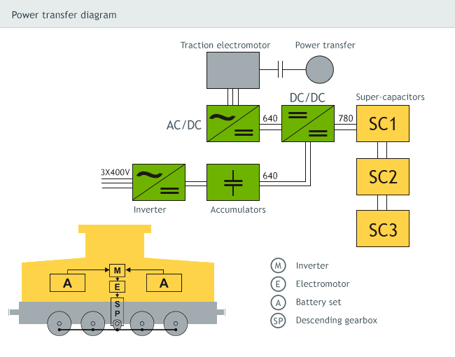
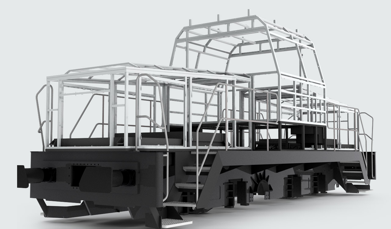
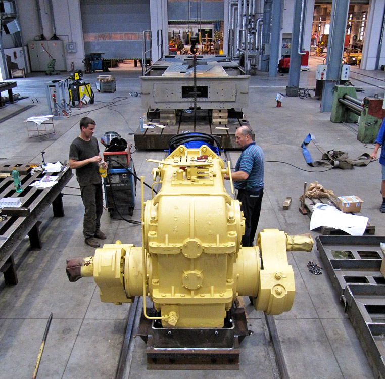
The vehicle was developed on grounds of as complete reconstruction of the original locomotive of 716 (V60) series. A completely new is the transfer of power – the original diesel-hydraulic set was replaced with the asynchronous traction motor and input planetary member of the original mechanical gearbox. This power transfer system using mechanical reduction box and coupling rods to individual wheel sets is especially suitable for the use in industry sidings. A high torque even at very low revolutions ensures the vector driven inverter allowing for electric power recuperation during the braking.
Benefits
- Asynchronous transfer of power
- Controlling torque through inverter with full vector control
- Åkerströms remote control device
- Forwarding route setup at local shunting circuit
- Recuperation of electric power
- Reduced regime for traction accumulators’ recharge
- Diagnostics of traction accumulators
- Remote access to control system during charging
- Evaluating energy balance
Cabin
Two new approaches along the diagonal walkways, which are optimal in terms of safety and ergonomics, were designed for a better access of the engine driver to the cabin. The cabin of the vehicle is equipped with a sandwich roof (so called tropic), which is apt to ensure the thermal comfort for the vehicle operator, in particular in the summer months.
Large windows along the longitudinal axis of the vehicle are designed with negative slopes and equipped with powerful windshield wipers. The engine driver’s control panels with the seats are located diagonally at both sides of the cabin. The cabin is heated by the Webasto independent heating system.
Power source
The lead traction batteries with nominal voltage of 640 V and capacity of 930 Ah. Altogether 320 battery cells in 8 containers was used. Maximum discharge of batteries represents 80 % of capacity, whilst their service life under the normal operation and 1500 re-charge cycles is roughly 10 years.
The electric power obtained during the locomotive’s braking with the use of electrodynamic brake is supplied back to the accumulators and super-capacitors that are used mainly during the increased consumption in the set of wagons start-up.
Equipment
The power electronics was placed inside built-in shelf located on one side in the space between the cabin and accumulators. A specific solution was applied to the cooling of the traction inverter by a liquid having a control loop for regulation of the temperature. To reduce the flange wear, the vehicle is equipped with modern flange lubrication system OK-02 fa TRIBOTEC – lubricant is subject to spraying directly upon flanges as they are rolling.
The sand trays are equipped with heated mixers that prevent the freezing of sand in adverse winter weather conditions. The sand blasting nozzles are heated too.
The locomotive is equipped with continuous electro-pneumatic brake DAKO BSE and direct-acting brake together with assistant parking brake circuit.
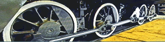
Driving gear
Download Type List »
Fill in the questionnaire for particular specification of the equipment »
Railway vehicles
| Questionnaire | Type List | Photo Gallery |
| Basic technical data A 415 | |
|---|---|
| Gauge | 1435 mm |
| Wheel Set Layout | D |
| Output Transfer | electromechanical střídavý |
| Width × Height × Length Across Buffers | 3027 × 4365 × 10970 mm |
| Length Across Wagon End walls | 9700 mm |
| Wheel Set Diameter | 1100 mm |
| Smallest Radius of Travel Arc | 80 m |
| Total Weight | 60 t |
| Rated output | 300 kW |
| Peak output for 90 sec. | 450 kW |
| Max. Operating Velocity | 30 km/hour |
| Max. Towing Force | 180 kN |
| Max. Direct Track Load | 2000 t |
| Max. Towing Force Use Range | 0 – 10 km/hour |
| Number of basic charging cycles | 1500 |
| Number of galvanic cells | 320 |
| Rated voltage | 640 V |
| Capacity | 930 Ah |


Mostárenská 2917/40
703 00 Ostrava-Vítkovice
Phone: +420 601 302 840
Czech Republic